


|
parameters2:Capacity: 10m3/day--200m3/day
parameters3:Material: Steel
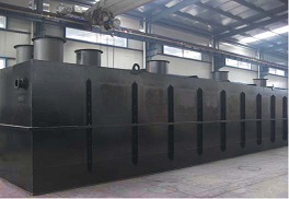
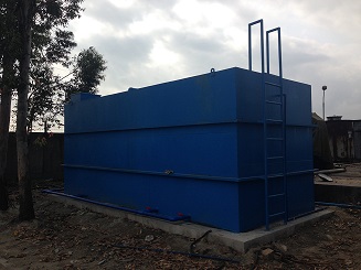
Installation underground Installation overground
Flow diagram:
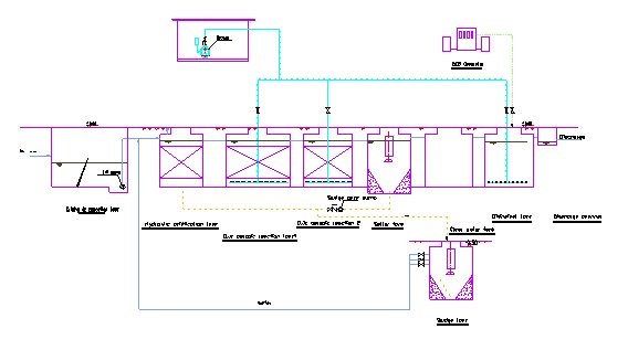
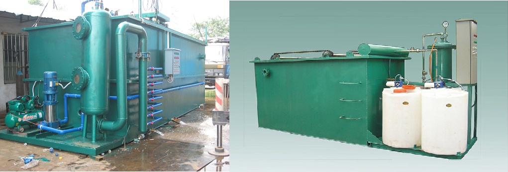
Treatment process :
The effluents flows into screen for big particles separating after collected by drain channel, then enters into adjusting tank for homogeneity and equant. A level controller is setted in the adjusting tank, who can deliver sign to CPU. The effluents were sent to A biological contact oxidation pond for acidification hydrolyzing and nitration-denitration in the order of reduce the concentration of organic matters and wiping and remove part ammonia nitrogen. After that enter into O biological contact oxidation pond for aerobiotic biochemical reaction. O biological pond is divided into two stages, and most organic contaminants are degraded by biological oxidation and adsorption. And now the effluents auto-flows to the second sediment pond for solid-liquid seperation. After that the upper clear liquid flows into disinfecting tank for bacterica remove by adding chlorinate chemicals. The disinfected clear liquid can be used for flower watering , toilet flushing, or discharge directly.
The sundries held back by the screen are collected by the truck and delivered to wasteyard regularly. The sludge in the second sedimentation tank , some reflux to A biological reaction tank and some are took off by the truck. The upper liquids of the sludge tank refluxs to adjusting tank for retreatment.
Package effluent treatment system main component:
|
NO. |
ITEM |
QTY. |
NO |
ITEM |
QTY. |
|
1 |
Screen |
1Pcs |
8 |
Sludge lifting equipment |
1Pcs |
|
2 |
Lift pump |
1Pcs |
9 |
Diffuser |
Pcs |
|
3 |
Level switch |
1Pcs |
10 |
Air blower |
1Pcs |
|
4 |
Containerized tank |
1Set |
11 |
Setter plate |
m2 |
|
5 |
Stuffing |
m2 |
12 |
ClO2 generator |
1Set |
|
6 |
Stuffing bracket |
1set |
13 |
Pipes&Valves |
1Set |
|
7 |
Manhole |
6Set |
14 |
Control box |
1Set |
Treatment capacity: